Coordinate motor power, brake, encoder and feedback interfaces.
Servo systems rely on multiple electrical paths with different current, noise and shielding needs. The connection plan must match motor and drive pinouts, separate power from feedback, and account for flexing between cabinet, machine and moving axes.
What the system must connect
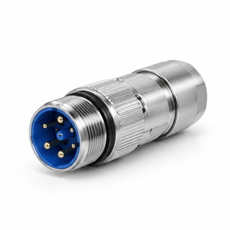
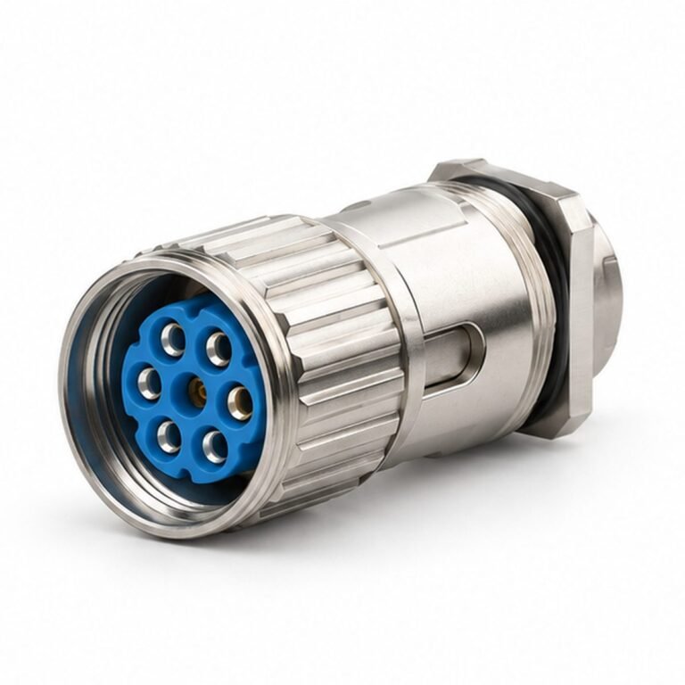
- M23 power connectors for motor power and protective earth.
- M23 signal interfaces for encoder, resolver, brake and feedback circuits.
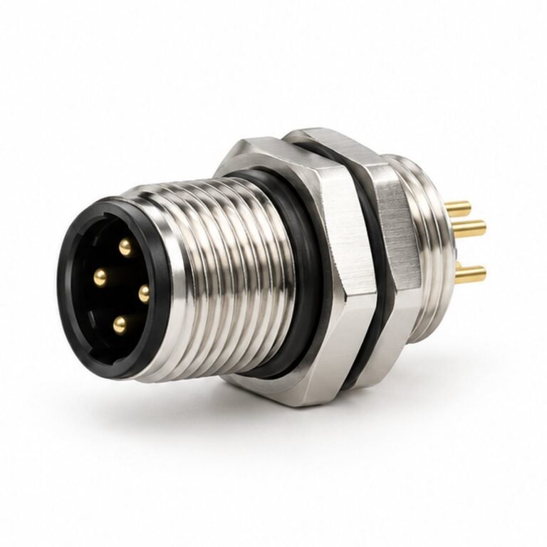
- M12 connections for auxiliary sensors and distributed motion I/O.
- Shielded high-flex cables between drive, motor and moving axes.
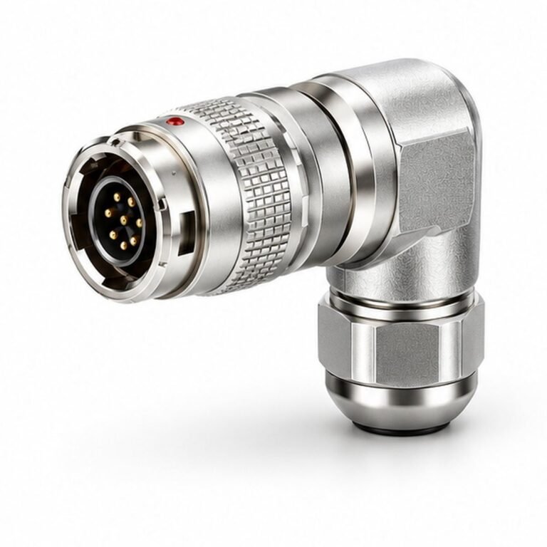
- Panel receptacles and right-angle exits matched to motor clearance.
Define before release
- Collect motor, drive, brake and feedback interface drawings.
- Confirm current, voltage, conductor size and grounding.
- Separate power and feedback shield paths and routing.
- Define flex duty, cable length, orientation and electrical tests.
Compatible LMConn products
Recommended product directions
These products are practical starting points for this application. Final pin count, coding, gender, cable and electrical ratings must be confirmed on the approved drawing.