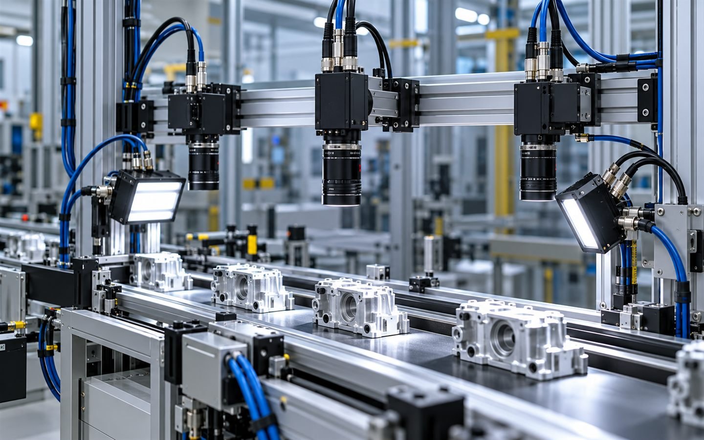
Build a controlled path for image data, trigger, lighting and power.
Industrial cameras often use separate high-speed data and I/O connections. A complete solution must preserve bandwidth, manage EMI, route moving cable safely and keep trigger and strobe signals aligned with the camera pinout.
What the system must connect
- GigE and industrial Ethernet cables for image transfer between camera and host.
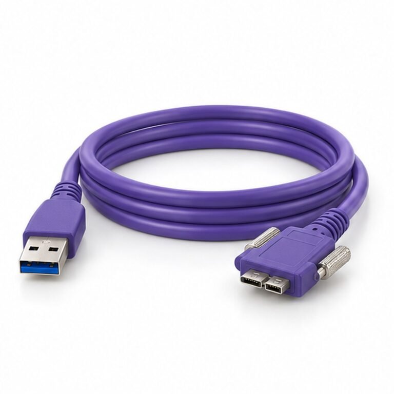
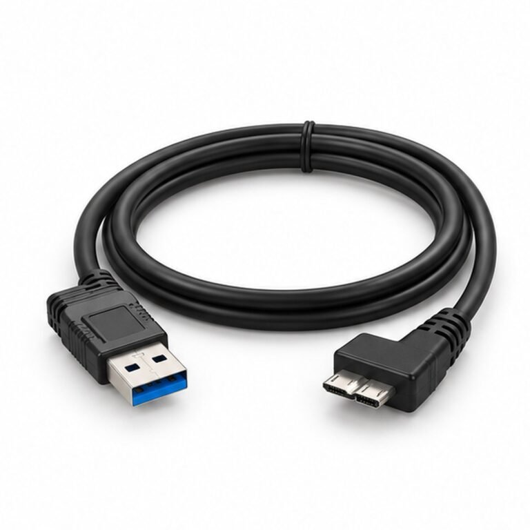
- USB 3.0 locking or right-angle assemblies where compact high-speed interfaces are required.
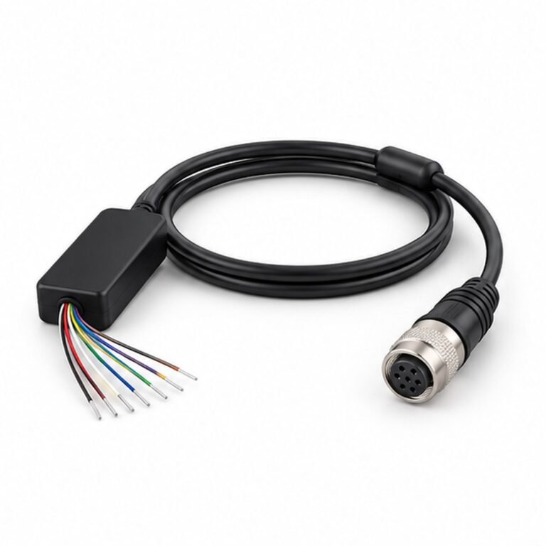
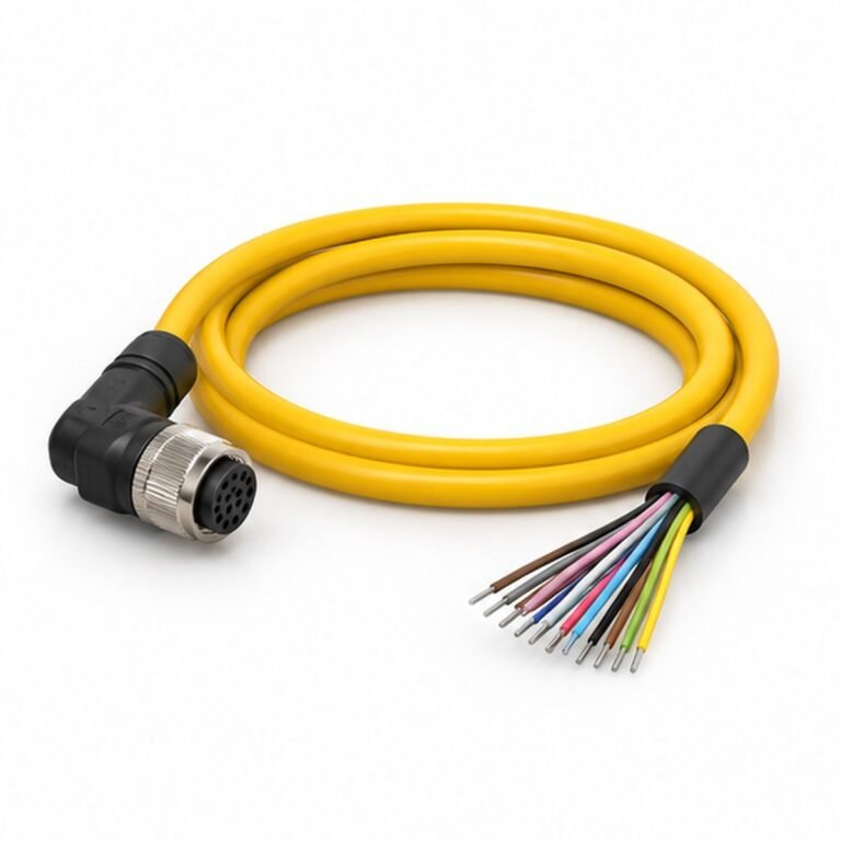
- 6-, 8-, 12- and 27-pin camera I/O cables for trigger, strobe, encoder and power.
- High-flex cable constructions for gantries, robot-mounted cameras and drag chains.
- Straight, right-angle and panel transitions matched to camera clearance.
Define before release
- Record the exact camera, controller and lighting model numbers.
- Separate image data, trigger, lighting control and power circuits.
- Define flex life, bend radius, travel, acceleration and cable carrier.
- Specify shielding, connector orientation, length and 100% electrical testing.
Compatible LMConn products
Recommended product directions
These products are practical starting points for this application. Final pin count, coding, gender, cable and electrical ratings must be confirmed on the approved drawing.