Explore every P Series configuration
18 product pages
Compare constructions, contact options and mounting formats.
P Series: construction and selection data
Reorganized from the applicable LMConn source-catalog pages. Final dimensions, contact ratings, keying and wiring remain controlled by the approved drawing.
Mechanical and environmental data
- Ingress protection
- Depends on selected body, seal and panel interface
- Mating endurance
- Confirm for the selected contact system
- Vibration
- Confirm against the approved application specification
- Mechanical shock
- Confirm against the approved application specification
- Salt-spray reference
- Material and finish dependent
- Temperature reference
- Connector, contact and cable material dependent
- Shielding reference
- Construction and cable dependent
Construction range
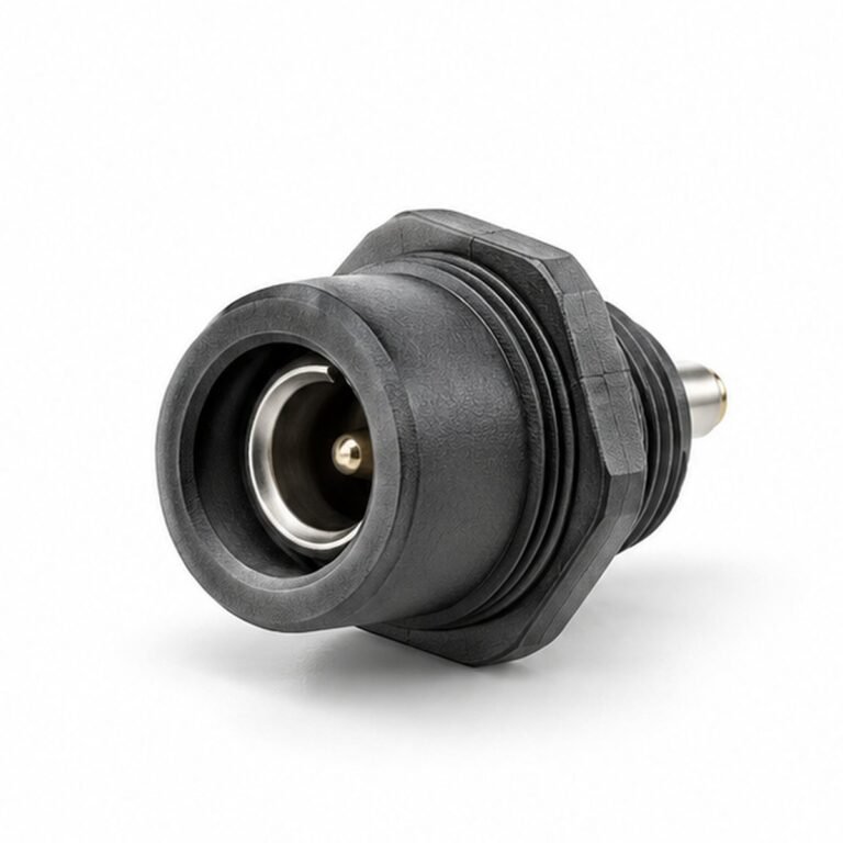
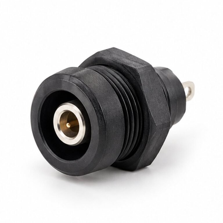
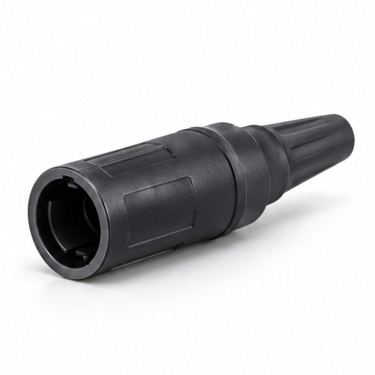
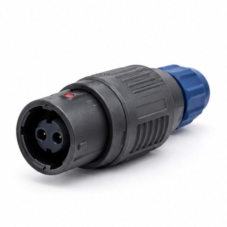
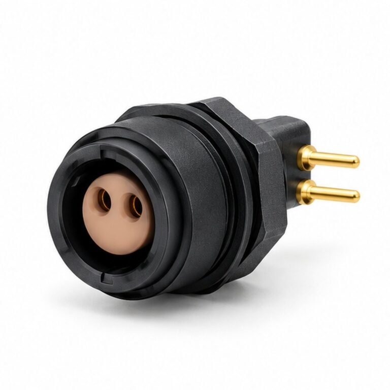
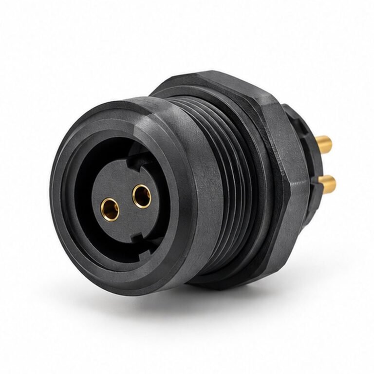
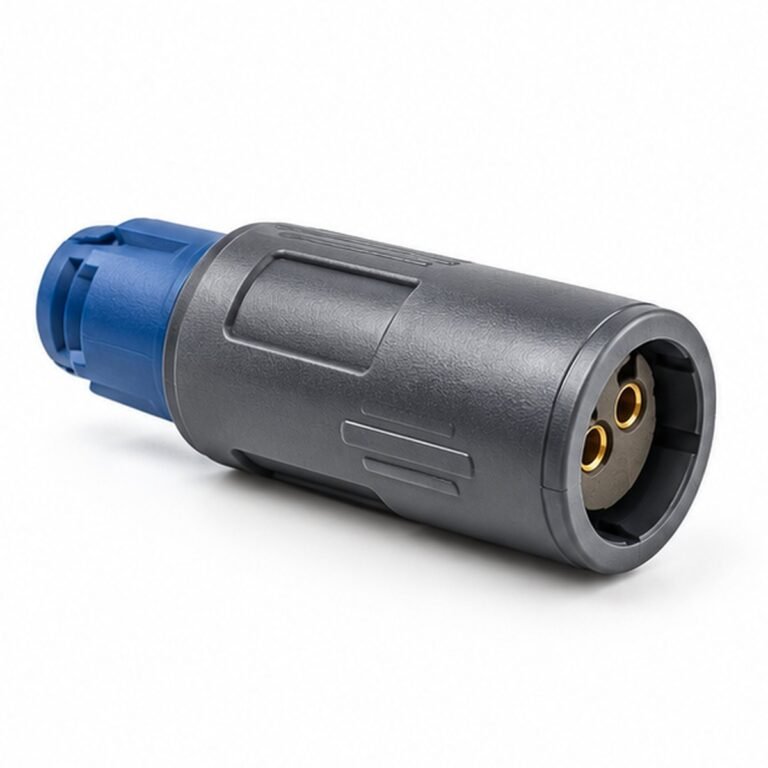
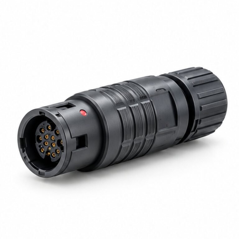
straight plastic plug, fixed plastic PCB receptacle, fixed plastic receptacle, coaxial straight plug, single-contact straight plug, coaxial fixed receptacle, single-contact fixed receptacle, floating plastic receptacle.
- Select plug, free receptacle, fixed receptacle, panel or PCB format.
- Confirm straight or right-angle cable exit and available installation space.
- Match the pin count, insert orientation, contact gender and keying to the mating component.
- Define solder, crimp, PCB or factory-molded cable termination.
- Release cable diameter, shielding, jacket, pin map and required tests on the drawing.
From connector format to a controlled configuration
- Body stylePlug or receptacle, straight, right-angle, panel or PCB construction.
- Key and shellKey orientation and shell-size family establish mechanical compatibility.
- InsertContact arrangement, contact gender and pin numbering define the electrical interface.
- MaterialsShell finish, insulator and contact material are selected for environment and duty.
- TerminationSolder, crimp, PCB, collet, cable nut or overmold completes the released build.
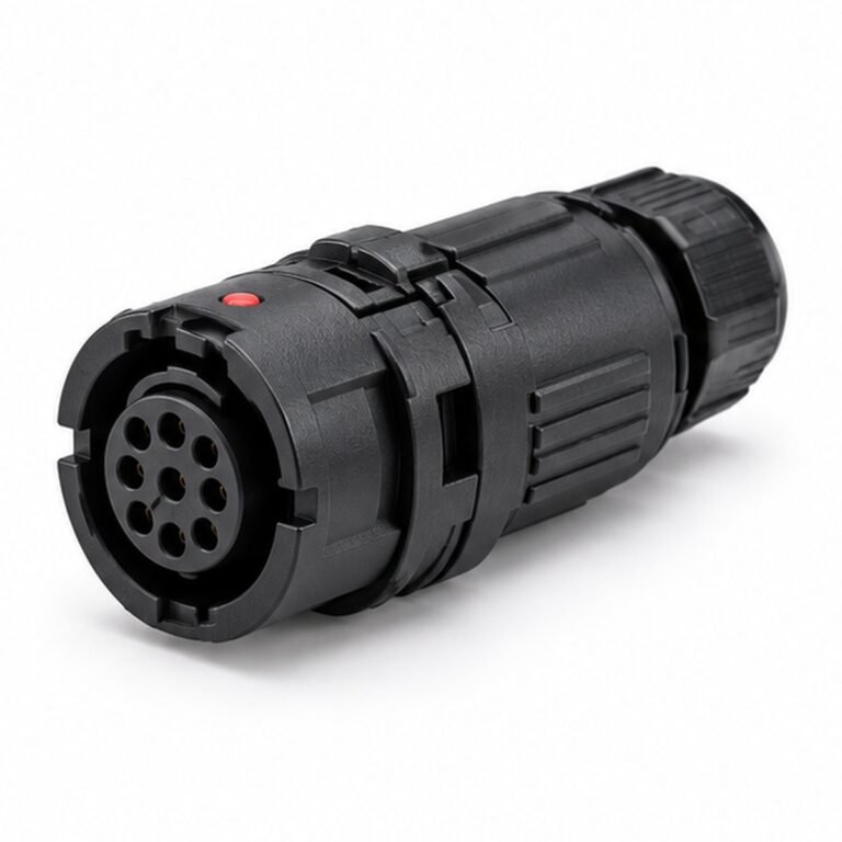

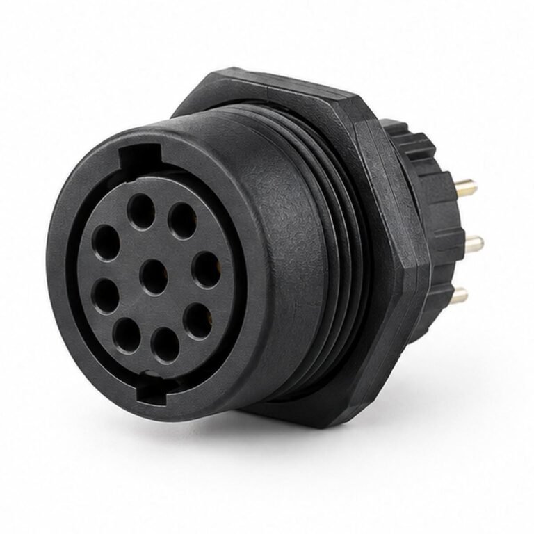


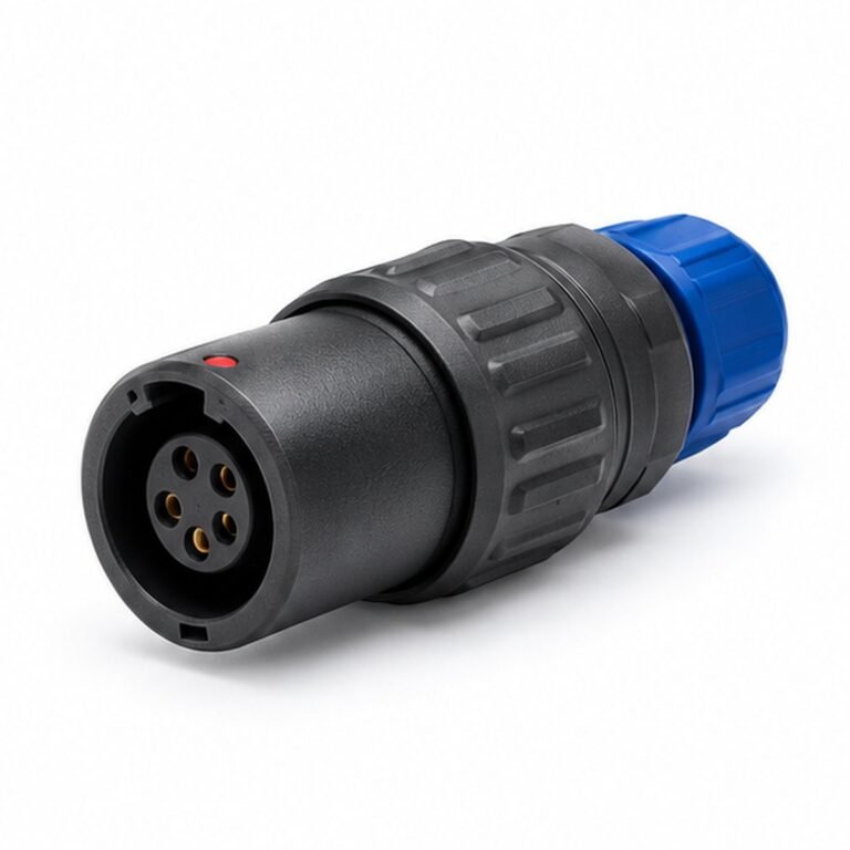
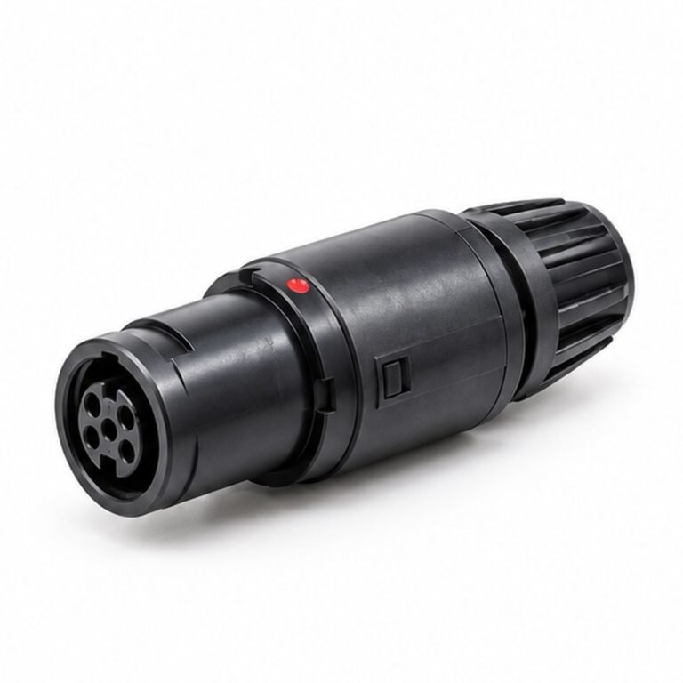


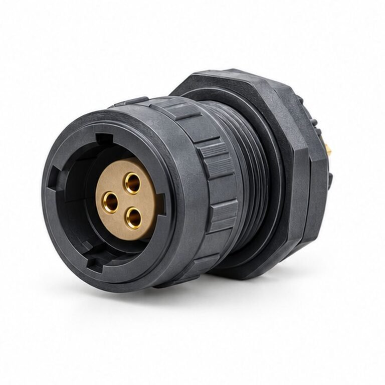
What P Series Plastic Push-Pull Connectors are designed to solve
The best result comes from matching the connector and cable to the complete system—not selecting by diameter or appearance alone. This page organizes the decisions an engineer, buyer or system integrator needs to make before requesting a drawing or quotation.
LMConn groups compatible formats by locking method, interface size, contact arrangement, installation method and cable construction. This makes it possible to compare standard options while keeping project-specific details such as pin mapping, cable length, labels and validation requirements under controlled revision.
Available product directions
0P multipole connector
Use this configuration when the equipment layout and mating interface call for 0p multipole connector. Confirm the exact drawing, electrical limits and mating component before release.
1P multipole connector
Use this configuration when the equipment layout and mating interface call for 1p multipole connector. Confirm the exact drawing, electrical limits and mating component before release.
2P multipole connector
Use this configuration when the equipment layout and mating interface call for 2p multipole connector. Confirm the exact drawing, electrical limits and mating component before release.
3P multipole connector
Use this configuration when the equipment layout and mating interface call for 3p multipole connector. Confirm the exact drawing, electrical limits and mating component before release.
Single-contact plastic connector
Use this configuration when the equipment layout and mating interface call for single-contact plastic connector. Confirm the exact drawing, electrical limits and mating component before release.
Catalog-derived parameters with original LMConn visuals
The following technical values are taken from the supplied source manuals rather than inferred from general connector practice. The accompanying image is an original LMConn presentation visual and is not a model-specific engineering drawing. Family-level data summarizes the catalog; ordering dimensions and electrical limits must still be checked against the exact model row and contact layout.
| Shell groups shown | 0P, 1P, 2P, 3P |
|---|---|
| Housing | Plastic circular connector construction |
| Formats | Straight plugs, fixed receptacles, floating receptacles and right-angle PCB receptacles |
| Contact styles | Multipole and single-contact versions |
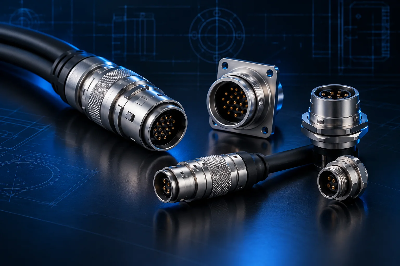
Product appearance varies by shell size, contact layout, mounting and cable configuration. Request the current model drawing and approved sample for final verification.
Engineering selection guide
- Choose shell size from contact count. Record the requirement in the interface-control drawing or RFQ so it can be verified.
- Confirm plastic material suitability. Record the requirement in the interface-control drawing or RFQ so it can be verified.
- Select straight or right-angle form. Record the requirement in the interface-control drawing or RFQ so it can be verified.
- Define solder or prewired termination. Record the requirement in the interface-control drawing or RFQ so it can be verified.
- Check mating retention and strain relief. Record the requirement in the interface-control drawing or RFQ so it can be verified.
Information that controls the design
| Decision | Questions to answer | Why it matters |
|---|---|---|
| Electrical | Signal, protocol, voltage, current, contact count and shielding? | Controls insert layout, contact size, cable and test plan. |
| Mechanical | Mounting, straight/angle exit, panel thickness, mating access? | Controls envelope, cutout and serviceability. |
| Environment | Dust, water, chemicals, temperature, vibration and mating cycles? | Controls sealing, material and strain-relief choices. |
| Cable | Static, flex, torsion, conductor size, jacket and outside diameter? | Controls backshell, gland, bend radius and lifetime. |
| Quality | Inspection, electrical test, labels, traceability and packaging? | Creates an objective acceptance standard. |
Important: Ratings differ by exact part number, contact layout, cable and assembly condition. Values shown on a family page are selection guidance, not a substitute for the approved product drawing and datasheet.
Typical applications and design priorities
Portable devices
For portable devices, engineers normally prioritize connection security, routing space and service access. Document the mating part and operating conditions so the connector, cable and termination can be evaluated as one system.
Disposable accessories
For disposable accessories, engineers normally prioritize signal integrity, environmental protection and repeatable installation. Document the mating part and operating conditions so the connector, cable and termination can be evaluated as one system.
Light industrial equipment
For light industrial equipment, engineers normally prioritize connection security, routing space and service access. Document the mating part and operating conditions so the connector, cable and termination can be evaluated as one system.
Measurement leads
For measurement leads, engineers normally prioritize signal integrity, environmental protection and repeatable installation. Document the mating part and operating conditions so the connector, cable and termination can be evaluated as one system.
Compact controllers
For compact controllers, engineers normally prioritize connection security, routing space and service access. Document the mating part and operating conditions so the connector, cable and termination can be evaluated as one system.
How to compare candidate products
Begin with non-negotiable interface requirements, then compare environmental and assembly details. Do not use a single headline rating as the sole decision. A suitable candidate should match the mating geometry, contact map, electrical load, cable construction, mounting envelope and maintenance method.
For replacement projects, send photographs only as supporting information. Measurements, existing part numbers, panel cutouts and pin assignments are needed because many circular connectors have similar external shapes. For new designs, reserve space for the connector body, coupling action, minimum cable bend radius and an operator’s hand or assembly tool.
RFQ checklist
- Target quantity, prototype quantity and annual demand.
- Connector family, mating component or interface drawing.
- Contact count, gender, coding, keying and pin assignment.
- Voltage, current, signal type, network protocol and shield strategy.
- Mounting method, panel thickness and available installation space.
- Cable type, length, conductor size, flex requirements and jacket material.
- Ingress protection, temperature, vibration and chemical exposure.
- Required tests, labeling, documentation and packaging.
Frequently asked questions
What is P Series Plastic Push-Pull used for?
P Series provides a lightweight non-metal housing option for applications where cost, touch feel, electrical insulation or equipment weight matters. Common uses include portable devices, disposable accessories, light industrial equipment. Final suitability depends on the selected part number and operating conditions.
How do I select the correct plastic push pull connector?
Start with the mating interface, electrical function and environment. Then confirm mounting, contact layout, termination, cable diameter and keying. The selection checklist on this page captures the minimum information needed for an engineering review.
Are all plastic push pull connector products interchangeable?
No. Products that look similar may differ in thread, shell size, keying, contact layout, insert orientation, sealing and dimensions. Always compare the complete dimensional drawing and mating-part definition.
Which specifications should I send for a quotation?
Send quantity, drawings or mating part, contact count, pinout, voltage and current, signal or protocol, cable type and length, environmental rating, mounting style and any testing or labeling requirements.
Can LMConn configure a custom version?
Configuration can cover contact layout, cable length, connector orientation, pin mapping, shielding, overmolding, labels and packaging where technically feasible. A drawing review is required before production.
How is the final part verified?
Verification should be defined by the project and may include dimensional inspection, continuity, insulation resistance, contact resistance, high-potential testing, shield continuity and visual checks. Required tests must be agreed in the specification.