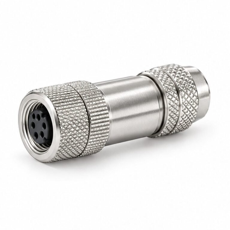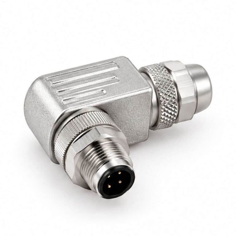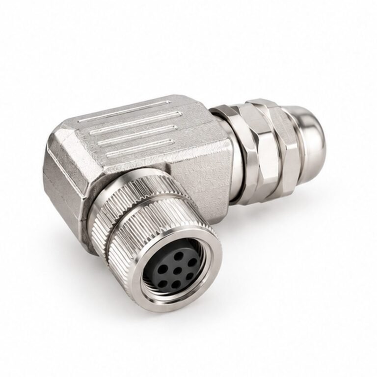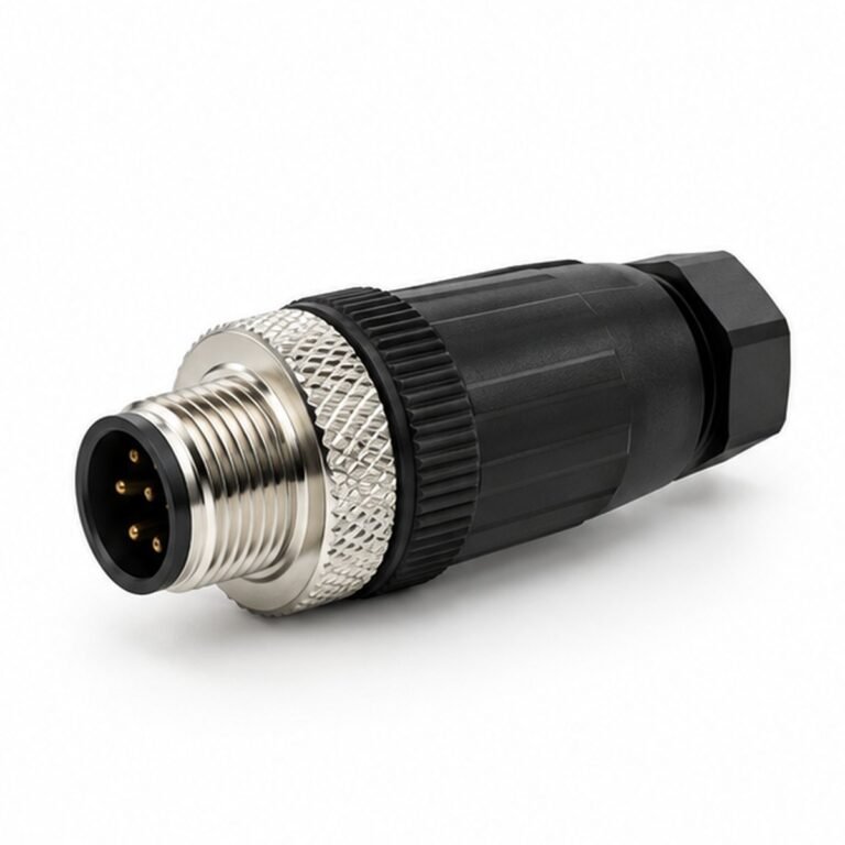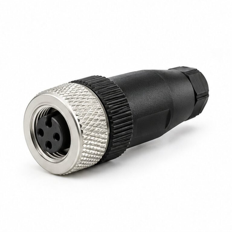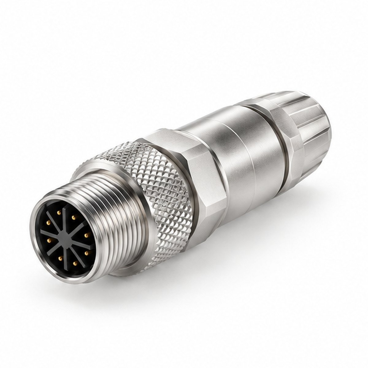
M12 X-Coded Field-Wireable Male Connector is a X-coded male field connector in the M12 range. It is intended for industrial automation, Ethernet, sensors and machine power, with the mechanical format selected around mating interface, installation space, cable routing and service access.
This page identifies the catalog construction and purchasing variables without treating a family-level value as a guaranteed part-number rating. The final contact layout, keying, pin assignment, cable and environmental performance must be released on the LMConn approved drawing.
Product configuration at a glance
- Construction: X-coded male field connector
- Interface: the specified mating interface
- Available pin counts: 8-pin
- Gender / mating side: Male
- Orientation: Orientation shown in the selected construction
- Termination: Field-wireable termination
Why engineers specify this construction
The X-coded male field connector form helps place the connection where cable bend radius, panel thickness, connector access and maintenance procedure are already defined. Within the M12 platform, engineers can keep a consistent mating concept while choosing the body style that suits the enclosure or harness.
For a repeatable build, provide the mating part, one of the listed contact configurations, pin map, electrical load, cable outside diameter, shielding, required ingress protection and expected quantity. LMConn can then review the connector, termination and cable as one controlled assembly.
Selection and integration notes
- Confirm that the plug or receptacle side matches the installed mating connector.
- Confirm contact count, insert orientation, coding and pin numbering before wiring release.
- Check rear clearance, panel cutout, cable bend radius and tool access.
- Specify cable jacket, conductor size, shielding, flex duty and overall length.
- Approve the dimensional drawing and wiring table before production.
Typical applications
This construction is a practical starting point for industrial automation, Ethernet, sensors and machine power. It may also be evaluated for test fixtures, control cabinets, sensor interfaces, imaging systems and custom equipment where a defined mechanical interface and controlled cable build are required.
Related engineering paths
Compare the complete M12 family, review custom cable assemblies, see a related application solution, or send the configuration directly through the request-a-quote form.
Source and release note
Catalog reference: Threaded circular connector manual, PDF page 13, printed page(s) 23-24. The catalog image and description establish the construction family; the approved LMConn drawing remains the release authority for dimensions, ratings and wiring.
Frequently asked questions
Can the contact count or cable be customized?
Yes, where the selected shell and insert support it. Send the mating part, pin count, pin map, cable type and operating environment for review.
Is the displayed product visual an exact production drawing?
No. The clean visual is a representative LMConn construction illustration. Production dimensions and connector details are controlled by the approved drawing.